
Opening the Box
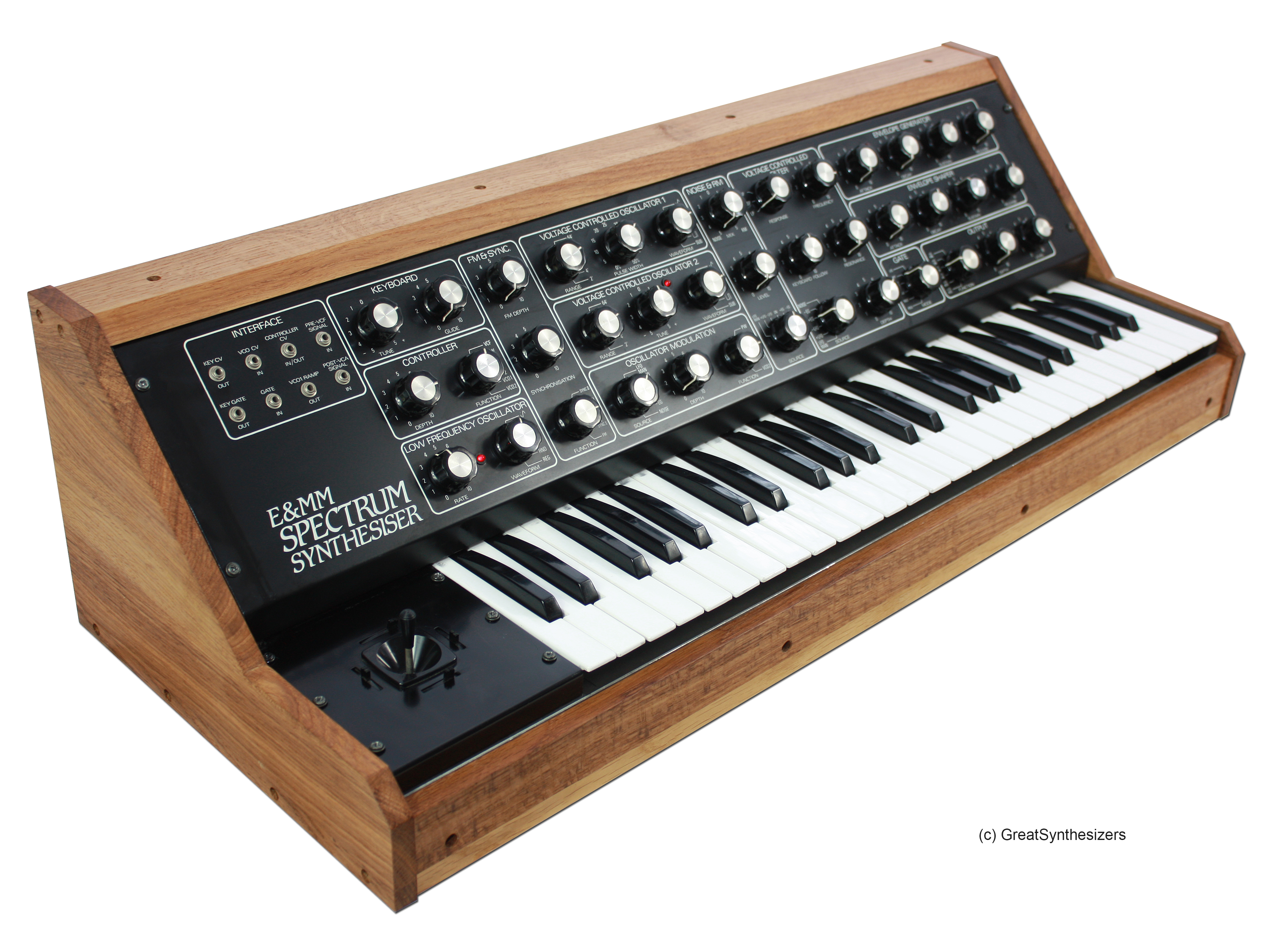
The first thing with a D.I.Y. project, is how much care did the original constructor put into the build. First impressions on this one were good, but this one was D.O.A.
It was suffering from a problem that mine had, the mechanical fixing of the p.c.b.s was long screws, with a spacer and a nut securing the board. The kit was not supplied with shake proof washers and the nuts work loose because of the long lever on the screw, allowing the boards move. With the wiring close to the fixings, poor cable prep could cause a short when the board moves. So task one secure the boards.
Initial Power Up
First job is to disconnect the internal PSU and connect up a lab PSU with current limiting. Good news, the current drawn on each rail is approximately what was expected. So step 2; with the PSU still disconnected and the AC in applied, only one side of the PSU was working. Check the fuses and bingo, one fuse is blown. With the fuse replaced the PSU is now working on both rails.
The trimmers are cleaned and the rails set to +15V and -15V, while still disconnected. Once the PSU is reconnected, the trimmers are adjusted to give +15V and -15 while powering the synth.
So we now have a working synth (ish). It sounds awful and is far from being in any sort of tune. Some keys don’t work and others give false triggers. Next up us the keyboard and controller circuit.
 Moog Voyager Modular Synth Interface is designed to bring all the controller outputs from the Voyager to 1/4″ Jack Sockets in a modular form. The control ranges can be set to be compatible with the system it is installed in.
 interface card on Yamaha 01V96i mixer. Configure a new input map that maintains the control surface as close as possible to the original layout. Document all changes.