Upgrade 01v96i Live Mixer to 32 Tracks
Task: Install and test a YAGDI 8 analogue input 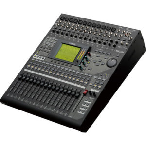 interface card on Yamaha 01V96i mixer. Configure a new input map that maintains the control surface as close as possible to the original layout. Document all changes.
The current setup was for a 5 piece band playing in small venues. With three vocalists, drums, bass, guitar and keys the initial setup was fairly ordinary. 12 inputs are used and just the onboard effects from the desk. This setup had been in use for some time, the band were now playing slightly bigger venues and wanted to mic all the drums and the control surface was to remain as unchanged as possible.
Current Input and Control Surface:
In Fade Desc   In Fade Desc   In Fade Desc
1   1   Vox1   2   2   Vox2   3   3   Vox3
4   4   Kick   5   5          6   6
7   7          8   8          9   9
10  10         11  11  BassDI 12  12  Gtr Mic
13  13  Keys1L 14  14  Keys1R 15  15  Keys 2L
16  16  Keys2R RCA 15  MusicL RCA 16  MusicR
The faders shown in RED had shared functionality, the incidental music with the second keyboard. The alternate RCA connectors switched in when required.
Card Installation:
The desk supports 24 channels, but 8 of these inputs are via the ADAT interface and are not usable as stage inputs, leaving just 16 physical inputs. An additional physical 8 inputs can be added by installing an optional interface card.
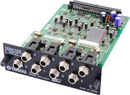
A second hand Yamaha MY8 AD24 card was sourced on a well know auction site. The card installation is straight forward. Power off remove the cover and plug it in. It was tested using the desks internal signal generator.
The the firmware in the desk was upgraded while the desk was being serviced. All channels and connector were checked ad cleaned.
Input and Fader Mapping:
Even though there is now 24 channels on the desk there are just 12 channels with XLR inputs. The new setup uses 12 mics, so all XLR inputs would be needed, 7 DIs and 2 RCA inputs for the incidental music. Most digital mixing desks have the ability to remap the inputs so that the input does not correspond to the fader. This mapping has been used to keep as much as possible of the original mapping.
In Fade Desc   In Fade Desc    In Fade Desc.
1   1   Vox 1  2   2   Vox2    3   3   Vox3
4   17  Kick   5   18  Snare   6   19  OHL
7   20  OHR    8   21  Tom1    9   22  Tom2
10  23  Tom3   11  24  Tom4    12  12  Gtr Mic
13  5          14  6           RCA 7   Music L
RCA 8   MusicR 17  9   Gtr DiL 18  10  Gtr DiR
19  4          20  11  Bass DI 21  13  Keys1L
22  14  Keys1R 23  15. Keys2L  24  16  Keys2R

7-11 Bus1 Drums L  7-11 Bus2 Drums R
The final mapping only moved the kick drum fader from 4 to 17. RED indicates changes, BLUE are new inputs and GREEN remain unchanged.
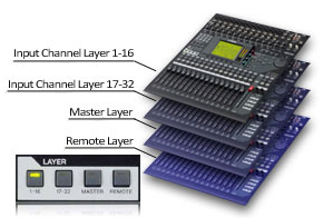 The drum faders are all on consecutive faders on the second layer from 17-23. These channels are mixed to Bus1&2, so the bus master can be used in the final mix. The music moved from a shared channel 15/16 to it’s own fader pair on channels 7&8.
There are 3 channels free, these have been mapped to unused faders on the first layer, arranged so a stereo pair can still be mapped if required.
Because the faders (with the exception of the kick drum) stayed in the same position, all the monitor mixes remained unchanged.
Self adhesive labels were added to the inputs and the faders to ensure that there was no confusion when operating the desk. The customer also received a laminated input patch diagram for reference, this can be left in the flight case with the mixer.
If you want to know how to do this yourself read our tutorial here